
Adhesive-Mounted Aerosol Fire Suppression for Electrical Cabinets

An adhesive-mounted aerosol fire suppression device is a compact unit fixed directly to a prepared surface inside an electrical cabinet or distribution box. The mounting method can simplify retrofit work where a DIN rail position or clip feature is unavailable, but the adhesive joint becomes a safety-critical installation interface. Selection must therefore address enclosure geometry, surface condition, temperature, vibration, activation method, discharge clearance, inspection access, and documented acceptance criteria.
For buyers comparing mounting options, the key question is not whether adhesive installation is convenient. It is whether the specified adhesive system, substrate, preparation method, installation pressure, curing or dwell time, and environmental limits have been verified for the intended cabinet. SUNIOIO industrial electrical solutions should be evaluated as part of the complete enclosure protection design, not as a substitute for project-specific fire engineering.
What adhesive mounting changes in the design
A self-adhesive fire suppression device transfers its mass and any service loads through a bonded interface rather than through a screw, rail clip, or structural bracket. The joint may look static, yet cabinet vibration, door impacts, thermal cycling, cable pull, cleaning agents, dust, oil film, humidity, and long-term creep can all reduce retention. A unit that remains attached during a short room-temperature sample inspection may not remain secure over the declared service environment.
The adhesive is only one part of the joint. Performance also depends on the cabinet coating, surface roughness, flatness, contamination, contact area, installation pressure, edge exposure, and the direction of loading. Powder-coated steel, painted sheet metal, stainless steel, aluminum, engineering plastic, and textured surfaces should not be treated as interchangeable. The supplier and buyer should identify the approved substrate families and the evidence used to support them.
Fire-suppression performance and mechanical attachment are separate acceptance questions. ISO 15779 addresses requirements and test methods for condensed aerosol system components and system design, installation, testing, maintenance, and safety. ANSI/CAN/UL/ULC 2775 covers fixed condensed aerosol extinguishing system units. Referencing a standard does not prove that a specific product or adhesive configuration is certified; request the actual report, listing, scope, and model relationship before making a compliance statement.
Adhesive, clip-on, and DIN rail mounting compared
Mounting option | Best-fit situation | Verification priority | Typical installation risk |
Adhesive-backed | Retrofit cabinets with a clean, flat approved surface and no suitable rail position | Substrate compatibility, surface preparation, dwell time, temperature, vibration and peel resistance | Contamination, coating failure, creep or edge lift |
Clip-on or snap-fit | A defined cabinet feature or dedicated bracket accepts the clip geometry | Retention force, tolerance stack, repeated removal, shock and vibration | Partial engagement or incompatible feature dimensions |
DIN rail-mounted | Cabinets with available compatible rail space and controlled component layout | Rail profile, clip engagement, spacing, orientation and conductor clearance | Crowded rail, wrong profile or interference with adjacent equipment |
The table is a selection framework, not a product rating. A buyer may prefer adhesive mounting for fast retrofit installation, while a panel builder may prefer DIN rail mounting for repeatable assembly and easier location control. Clip-on mounting can be efficient when the cabinet has a compatible feature. The final choice should be made from the approved model drawing, installation instructions, enclosure layout, and validated environmental range.
Cabinet survey before selecting an adhesive-mounted unit
Start with the protected enclosure, not the extinguisher label. Record internal width, height, and depth; occupied component volume; ventilation openings; cable entries; partitions; door seals; likely fire locations; energized equipment; maintenance access; and any airflow created by fans. A nominal cabinet size does not describe the actual free volume or the routes through which suppressant may escape.
Mark candidate mounting areas on the drawing. Exclude locations that obstruct breakers, terminals, busbars, ventilation paths, door mechanisms, labels, emergency access, or required electrical clearances. Confirm that the device and activation element cannot be damaged by routine wiring work. Discharge openings need the model-specific clearance stated by the manufacturer; never invent a universal distance or aim the outlet at heat-sensitive components without evidence.
The cabinet temperature range must include normal operation, solar loading, nearby heat-producing components, shutdown conditions, transport, and storage. Adhesive behavior can differ at low and high temperatures, and the cabinet substrate may expand differently from the device housing. If and corrosion should be part of the survey where equipment is installed outdoors, in washdown zones, near chemicals, or in coastal environments.
Surface preparation and installation workflow
A controlled installation process should be written before production or field deployment. Generic instructions such as “clean and stick” are not sufficient because they do not define the cleaning material, acceptable surface, installation pressure, minimum temperature, or waiting period before the joint is loaded.
Verify the exact device model, mounting kit, adhesive lot or part number, approved orientation, activation method, and cabinet application against the approved submittal.
Confirm that the proposed substrate and coating are included in the supplier's compatibility evidence. Do not bond over loose paint, rust, dust, oil, silicone contamination, condensation, labels, seams, sharp texture, or an unapproved plastic.
Isolate electrical equipment and follow the site's lockout, access, and fire-system impairment procedures. Installation inside energized equipment should only be performed under an approved safe-work method.
Prepare the surface using the product-specific method. Record the cleaning agent, cloth type, number of passes, drying time, surface temperature, ambient temperature, and visual acceptance result.
Use a simple positioning template so the device is placed at the approved location and orientation. Avoid touching the bonding surface after the liner is removed.
Apply the specified pressure over the full bond area for the stated duration. Record installation time and installer identification. Respect any required dwell or cure period before attaching cables, closing the door, transporting the cabinet, or accepting the installation.
Route the thermal or electrical activation element exactly as shown in the approved design. Provide strain relief so the cable cannot peel the device from the surface.
Inspect edge contact, alignment, discharge clearance, cable routing, component access, and labels. Photograph the completed installation from a repeatable viewpoint.
Example adhesive-mount acceptance matrix
The following matrix turns installation claims into records. Test methods and limits must be agreed for the actual model, adhesive, substrate, orientation, and destination requirements. Values below are intentionally not prescribed because an unsupported universal limit would be misleading.
Check | Evidence to record | Acceptance basis |
Identity | Device model, mounting kit, adhesive lot, substrate and coating | Approved bill of materials and drawing |
Surface condition | Cleanliness, damage, flatness, temperature and preparation method | Product-specific installation instruction |
Location | Coordinates, orientation, discharge clearance and component access | Approved cabinet layout |
Bond installation | Pressure method, application time, dwell time and installer | Validated work instruction |
Retention | Defined proof-load, direction, duration and post-check | Engineering test plan for the assembly |
Environment | Thermal cycle, humidity, vibration or chemical exposure as applicable | Declared service conditions and qualification plan |
Functional interface | Activation continuity or thermal-element placement without discharge | Manufacturer procedure and system cause-and-effect |
Final inspection | No edge lift, cable peel load, obstruction or label conflict | Released inspection checklist |
Activation and system integration
Condensed aerosol units may use thermal, electrical, or other approved initiation arrangements. The exact product configuration determines how detection, supervision, alarm, isolation, delay, manual release, and status feedback are handled. An adhesive mounting method does not change those system responsibilities. The installer must follow the listed or approved system design and the authority having jurisdiction.
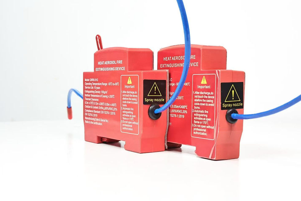
For electrically initiated systems, document the control voltage, current, circuit supervision, cable type, routing, fault response, and interface to the fire alarm or equipment shutdown logic. For thermally activated arrangements, document the activation element location, routing, securing method, temperature rating, separation from normal heat sources, and replacement requirements. Do not describe a product as automatic solely because a thermal cord appears in a photograph; verify the model documentation.
NFPA 2010 is titled Standard for Fixed Aerosol Fire-Extinguishing Systems and provides a recognized reference point for fixed aerosol system design and safety discussions. Project requirements may also involve electrical, fire alarm, machinery, enclosure, battery, or local building rules. A competent designer should identify the applicable requirements and approval path for the installation location.
Buyer and supplier audit questions
Which exact models are available with adhesive, clip-on, and DIN rail mounting, and are the suppression unit and mounting accessory controlled under one bill of materials?
What cabinet substrates, coatings, orientations, temperatures, humidity levels, vibration conditions, and storage periods have been evaluated for the adhesive version?
Does the quoted evidence apply to the finished production model, or only to an adhesive coupon or engineering prototype?
What surface-preparation materials, installation pressure, dwell time, minimum application temperature, inspection method, and rework procedure are required?
How are adhesive material, liner, device housing, activation component, labels, packaging, and finished units lot-traced?
What change-control process prevents an unapproved adhesive, coating, housing material, or supplier substitution?
What records are supplied with production lots, and what incoming checks can the buyer repeat without discharging the unit?
Which certification or test reports are current, which models and mounting variants are covered, and which marketing statements are outside their scope?
For OEM work, send the cabinet drawing, internal layout, free volume, substrate and coating specification, temperature and vibration conditions, mounting orientation, activation concept, destination market, quantity, labeling, packaging, and required evidence. A useful quotation should identify assumptions and unresolved items rather than quietly assigning a generic device to every enclosure.
Common installation mistakes
The most common mistake is treating adhesive mounting as a cosmetic attachment. Other failures include bonding to dusty powder coat, locating the device on a removable cover without considering cable strain, installing below a condensation path, allowing the activation cable to create peel load, blocking a discharge opening, skipping the dwell period, and accepting an installation without photographs or traceability.
Another error is copying claims from a catalog or image. Statements such as non-toxic, zero residue, maintenance-free, safe for all electronics, environmentally friendly, or capable of stopping lithium-ion thermal runaway require specific evidence. In battery cabinets, distinguish an incipient fire in auxiliary electrical equipment from propagation or thermal runaway within cells. Do not extend a cabinet-fire test beyond its actual scope.
Frequently asked questions
Can an adhesive-mounted aerosol extinguisher be installed on any electrical cabinet?
No. Suitability depends on the approved device model, substrate, coating, cleanliness, flatness, orientation, temperature, vibration, moisture, cable loads, discharge clearance, activation arrangement, and applicable approval requirements. Verify the complete bonded assembly rather than the adhesive name alone.
Is adhesive mounting better than DIN rail mounting?
Neither method is universally better. Adhesive mounting can support retrofit work on a suitable flat surface. DIN rail mounting can provide repeatable mechanical engagement where compatible rail space exists. Clip-on mounting can work with a defined bracket or cabinet feature. Compare layout constraints and validation evidence.
How should a bonded device be inspected?
Record model identity, adhesive and substrate, preparation conditions, location, orientation, edge contact, cable strain relief, discharge clearance, dwell time, and installation photographs. Add environmental and retention checks according to the approved test plan, then define replacement criteria for disturbed or damaged bonds.
Can this device be promoted as compliant with ISO, NFPA, or UL requirements?
Only when current documentation identifies the exact product, mounting variant, scope, test basis, and permitted wording. A standard reference in an article is not certification. Buyers should review the original certificate, listing, report, model schedule, limitations, and issuing organization.
Authoritative references
ISO 15779:2026, Condensed aerosol fire extinguishing systems — requirements and test methods for components and system design, installation and maintenance.
NFPA 2010, Standard for Fixed Aerosol Fire-Extinguishing Systems.
ANSI/CAN/UL/ULC 2775, Standard for Fixed Condensed Aerosol Extinguishing System Units.
Contact SUNIOIO
For mounting-option selection, OEM documentation, samples, drawings, and quotation review, contact SUNIOIO / Yueqing Zhaoqing Electric Co., Ltd. Send the cabinet layout, substrate and coating, environmental conditions, activation concept, quantity, destination market, and required test evidence. Phone / WhatsApp / WeChat: +86 13588953026. Visit SUNIOIO services or use the SUNIOIO contact page.


留言