
DIN Rail Aerosol Fire Extinguisher Installation for Control Cabinets

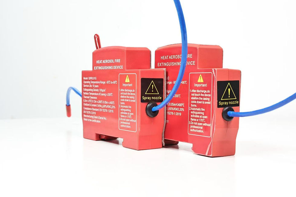
A DIN rail aerosol fire extinguisher is a compact automatic fire-suppression device mounted inside an electrical enclosure on a rail-compatible carrier. The mounting method can reduce drilling and simplify repeatable assembly, but it does not by itself prove fire performance, electrical compatibility, or suitability for every cabinet. Selection still depends on the device's verified installation drawing, protected enclosure, activation method, discharge clearances, environmental limits, and evidence accepted by the relevant authority.

This guide explains how panel builders, electrical-equipment OEMs, distributors, and maintenance teams can review a DIN rail-mounted fire suppression device without turning a convenient mounting feature into an unsupported safety claim. It focuses on cabinet layout, rail retention, electrical spacing, acceptance checks, and the evidence a buyer should request before volume approval.
Confirm what “DIN rail-mounted” actually means
DIN rail is a family of standardized support profiles used for electrical and control equipment. A product description should identify the compatible rail profile and mounting interface rather than simply saying “DIN rail.” Only describe a device as compatible with 35 mm rail when the current product drawing and test evidence confirm that interface. The rail width alone is not enough: rail height, thickness, slot pattern, edge geometry, coating, mounting orientation, and available end restraint can affect fit.
The fire-suppression unit may attach directly to the rail, use a separate adapter, or engage a bracket fixed to the rail. Record every part number in the approved bill of materials. If an adapter is required, treating it as generic hardware creates a change-control gap. Material stiffness, latch geometry, heat exposure, and vibration resistance may differ even when two adapters look similar.
IEC 60715 describes dimensions for low-voltage switchgear and controlgear mounting on standardized rails. It is useful for defining the mechanical interface, but compliance with a mounting-rail standard is not evidence that the extinguishing device is approved for a specific cabinet or fire hazard. Fire protection and electrical construction requirements must be reviewed separately.
Survey the cabinet before selecting a mounting position
Begin with a dimensioned cabinet survey. Record enclosure width, height, depth, door swing, internal barriers, rail positions, cable ducts, terminals, contactors, power supplies, heat-producing components, ventilation openings, gland plates, and service-removal paths. Identify energized parts and the required electrical clearances for the equipment and destination market.
Do not choose a position only because an empty section of rail is visible. The device must not block breaker operation, terminal access, labels, ventilation, thermal management, wiring bend radius, or the removal of adjacent components. Confirm that technicians can inspect the unit without dislodging it during normal service.
The protected volume also needs a separate review. Gross cabinet dimensions do not automatically equal the design volume. Internal partitions, open cable entries, ventilation fans, louvers, door gaps, and connected ducts can influence retention of the extinguishing aerosol. Obtain the manufacturer's application method and product-specific design data instead of extrapolating from agent mass or shell size alone.
Use a rail-and-cabinet compatibility matrix
Create a controlled matrix for every proposed enclosure family:
| Review item | Evidence required | Reject or escalate when | | --- | --- | --- | | Rail profile | Cabinet drawing and measured production sample | Profile is assumed from appearance | | Mounting interface | Device and adapter drawing with revision | Adapter identity or tolerances are missing | | Retention | Approved pull, shock, and vibration method | Unit rocks, migrates, or releases | | End movement | End stop or other defined restraint | Device can slide into live equipment | | Discharge clearance | Manufacturer's installation envelope | Wiring or barriers obstruct the defined region | | Electrical spacing | Cabinet layout and applicable design rules | Mounting compromises creepage or clearance | | Thermal exposure | Measured maximum local temperature | Location exceeds a verified device limit | | Service access | Maintenance and isolation procedure | Routine work can damage or remove the unit |
This matrix is a project worksheet, not proof that all DIN rail aerosol fire extinguishers fit all cabinets. Freeze the rail, adapter, device, enclosure, and drawing revisions after validation. Reassess the installation when the cabinet supplier, rail source, coating, internal layout, device housing, activation element, or adapter tooling changes.
Review placement and discharge clearances
Follow the device manufacturer's defined orientation and clearance envelope. Keep the discharge region free from bundled conductors, plastic wire duct, labels, insulating sheets, service loops, and movable mechanisms. A unit hidden behind dense wiring may be mechanically secure but poorly placed for the intended local application.
Consider heat sources and fault locations. Mounting beside a transformer, resistor, power semiconductor, or heavily loaded terminal may expose the device to a higher normal temperature than a cabinet-average reading suggests. Measure local conditions during representative load, at the maximum declared ambient, with doors and covers in their normal state. Do not confuse a thermal activation threshold with an allowable continuous storage temperature.
If the activation arrangement uses a thermal cord or separate detector, route it according to the approved instructions. Protect it from abrasion, unintended heat, sharp edges, maintenance tools, and accidental tension. Never demonstrate activation on a live unit with an improvised flame or hot-air test.
Control electrical and mechanical risks
The installation must not create a conductive bridge, sharp edge, loose part, or obstruction near energized components. Review the mounting adapter for bonding needs, insulation, surface finish, fastener retention, and conductor abrasion. Maintain the electrical clearances required by the cabinet design and applicable equipment rules.
Rail-mounted components can move laterally if end restraint is missing. Define whether the device requires an end stop, dedicated rail section, locking feature, or secondary retainer. Check the assembled cabinet in all transport and operating orientations. Hand pressure is not a substitute for representative shock and vibration validation.
Use production-intent rails and tolerances during qualification. Test minimum and maximum rail thickness, adapter tolerance, installation force, complete engagement, removal force, transport vibration, mechanical shock, temperature exposure, humidity where relevant, and service cycles. Document the acceptance criteria before the test rather than deciding after seeing the result.
Installation and acceptance procedure
Confirm the exact device, adapter, rail, enclosure, activation parts, and drawing revisions against the approved bill of materials.
Isolate the cabinet according to the equipment manufacturer's lockout procedure and verify the required safe condition.
Inspect the rail for correct profile, secure fastening, burrs, deformation, contamination, coating damage, and sufficient end restraint.
Check orientation, protected space, discharge clearance, wiring, ventilation, local temperature, service access, and electrical spacing.
Engage the device or adapter using the documented direction and tool. Confirm the defined seated or locked indication.
Apply only the approved non-destructive retention check. Record rocking, sliding, incomplete latching, distortion, or damage as a deviation.
Install and inspect the activation arrangement by the manufacturer's procedure. Do not perform an improvised discharge or heat test.
Photograph the completed installation and record cabinet ID, device model, batch or serial identity, rail/adapter revision, installer, date, and inspection result.
For first-article qualification, use a representative cabinet at production tolerances and include fully routed wiring. Repeat the inspection after transport simulation and environmental exposure. A released latch, shifted unit, cracked housing, damaged rail, obstructed discharge region, or contact with energized parts is a failed condition until formally dispositioned.
Incoming inspection and maintenance
Incoming inspection should verify device and adapter identity, critical dimensions, housing condition, labels, leads, activation components, and packaging. Use a go/no-go gauge if the rail interface is critical and production volume supports it. Keep approved samples and photographs that show complete engagement.
After installation, inspect the device after cabinet transport, rewiring, short-circuit repair, water ingress, impact, unusual heating, or replacement of the rail. Routine records should show that the unit remains seated, unobstructed, dry, undamaged, and within the manufacturer's service requirements. Do not repeatedly remove and reinstall a latch unless the supplier defines the allowed cycles and inspection criteria.
Supplier evidence and procurement questions
Ask the supplier for the installation drawing, compatible rail profile, adapter bill of materials, orientation limits, discharge envelope, activation instructions, environmental limits, retention validation, maintenance requirements, traceability, and change-control process. If a listing, certificate, or test report is offered, confirm the exact model, configuration, standard edition, issuing body, scope, and validity.
ISO 15779:2026 addresses requirements and test methods for condensed aerosol system components and recommendations for design, installation, testing, maintenance, and safety. NFPA 2010 covers fixed aerosol fire-extinguishing systems. UL Solutions identifies ANSI/CAN/UL/ULC 2775 for fixed condensed aerosol extinguishing system units. These references establish evidence categories; they do not justify claiming that an unverified unit is certified or suitable for a particular cabinet.
The purchase specification should define approved device and adapter revisions, rail interface, cabinet families, sample tests, production checks, traceability, packaging restraint, nonconformance handling, and notification before any material or process change. A low unit price does not compensate for an undocumented mounting interface or unsupported protection claim.
Frequently asked questions
Is every 35 mm rail compatible with the same fire-suppression device?
No. The complete rail profile, thickness, geometry, mounting orientation, adapter, tolerances, and retention method must match the verified product arrangement. Confirm the current drawing and production sample.
Can a DIN rail aerosol device be installed next to any breaker?
No. The installation must preserve electrical spacing, breaker operation, wiring access, ventilation, discharge clearance, thermal limits, and maintenance access. Review the complete cabinet layout.
Does rail retention prove extinguishing performance?
No. Mechanical retention is one part of installation acceptance. Protected volume, enclosure leakage, hazard, activation, placement, product evidence, and authority requirements still need separate review.
References and contact
For model selection, send the cabinet drawing, rail profile, internal dimensions, operating environment, destination market, quantity, installation preference, and required evidence through the SUNIOIO contact page.
SUNIOIO / Yueqing Zhaoqing Electric Co., Ltd. Phone / WhatsApp / WeChat: +86 13588953026


留言