
MCB Distribution Box Aerosol Fire Suppression: Layout and Acceptance Guide

An MCB distribution box aerosol fire suppression system is a compact, automatically activated device selected for a specific enclosed electrical hazard. It can discharge extinguishing aerosol inside the enclosure during an incipient fire, but it does not replace correct conductor sizing, terminal torque, circuit protection, inspection, or the building fire strategy. The decisive question is whether the device, activation method, mounting arrangement, and enclosure conditions have been validated together.
This guide explains how to define that application without turning a product photograph into an engineering specification. It focuses on low-voltage MCB distribution boxes, including compact wall-mounted boards, modular consumer units, and small industrial branch-circuit panels. Every final design must follow the selected product's manufacturer instructions, applicable electrical and fire rules, and approval requirements in the destination market.
Why a Distribution Box Needs a System-Level Review
A distribution box concentrates protective devices, terminals, busbars, conductor bends, and cable entries within a small enclosure. A loose termination, damaged insulation, contamination, or abnormal loading can create heating or arcing. The MCB protects the circuit within its rated operating characteristics, but it is not a detector or extinguishing device for every internal fault.
Adding compact fire suppression changes the assembly. The unit must not block MCB handles, reduce required clearances, interfere with wiring, obstruct ventilation, or prevent inspection. The mounting method must suit the enclosure material, service temperature, vibration, and maintenance environment. Position the activation element according to the verified design, not intuition.
IEC 61439-1 provides general rules for low-voltage switchgear and controlgear assemblies, including construction, service conditions, technical characteristics, and verification. IEC 61439-2 adds requirements for power switchgear and controlgear assemblies. These references are useful when discussing the distribution-box assembly, but they do not by themselves approve an aerosol device or a modified panel. The party responsible for the final assembly must assess the modification and maintain the required evidence.
Confirm the Fire-Suppression Application Before Selecting a Device
The first purchasing document should describe the protected enclosure, not just request a price for a "distribution box fire extinguisher." Record the enclosure's internal dimensions and calculate gross internal volume. Then identify space occupied by MCBs, busbars, cable ducts, power supplies, terminals, and other components. Do not subtract occupied volume or choose an extinguishing quantity unless the selected system's design method explicitly allows it.
Photograph the enclosure open and closed. Mark cable entries, vents, door gaps, unused knockouts, and penetrations. Leakage and ventilation can affect agent retention and the suitability of a total-flooding concept. ISO 15779:2026 addresses condensed aerosol components, design, installation, maintenance, and safety. Its scope notes that local applications require a pre-engineered, pre-designed system tested and approved for the specific application. Buyers should ask what evidence supports the proposed configuration rather than assume a general rating covers every box.
The survey must also state whether the conductors remain energized after activation. Define the upstream isolation method, who can operate it, and whether a signal from the suppression system is intended to trip a contactor or breaker. Never infer an isolation function from the aerosol unit alone. If electrical shutdown is required, the interface, voltage, current, fail state, supervision, and reset procedure must be documented and tested as a separate control function.
Distribution Box Survey Sheet
Use one completed sheet for every enclosure type in a project. A change in enclosure size, vent pattern, component layout, or mounting surface may create a new configuration that needs review.
Survey field: What to record | Why it matters
Enclosure identity: Drawing number, location, manufacturer, model, material | Links the protection design to a controlled asset
Internal dimensions: Width, height, depth, gross volume | Establishes the physical boundary for selection
Electrical duty: AC or DC, system voltage, main rating, circuit count | Defines the electrical environment without assuming extinguishing suitability
Internal layout: MCB rows, busbars, terminals, cable ducts, spare ways | Identifies obstructions and available mounting zones
Openings: Cable glands, knockouts, vents, door gaps, fan openings | Supports enclosure-integrity and retention review
Ambient conditions: Minimum and maximum temperature, humidity, dust, vibration | Screens the device, activator, wiring, and mounting method
Operating access: Handle movement, labels, test access, cover removal | Prevents the added device from defeating normal operation
Isolation strategy: Upstream device, control interface, manual procedure | Separates extinguishing action from energy isolation
Approval basis: Product instructions, test report scope, authority requirements | Shows what evidence applies to this exact configuration
Maintenance owner: Inspection interval, responsible role, record location | Keeps the installed system traceable after handover
Choose the Mounting Method Around the Enclosure
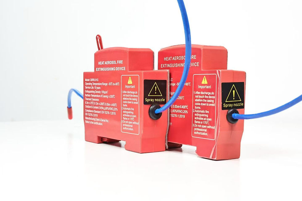
Compact aerosol devices may be offered with clip-on, DIN-rail, or adhesive mounting. These are not interchangeable conveniences. Each option creates a different mechanical interface and inspection requirement.
Clip-on mounting can suit a defined enclosure feature or bracket when both parts are designed to engage positively. The buyer should confirm the compatible profile, retention direction, removal method, vibration resistance, and whether the clip can be re-used after service. A generic statement such as "snap fit" is not enough for a project specification.
DIN-rail mounting can give a controlled position and a familiar service method in modular distribution equipment. Verify the rail size, available length, device width, clearances, orientation, locking feature, and effect on adjacent MCBs and wiring. A rail-mounted device must not be mistaken for a protective switching device, and its label should remain visible without obscuring circuit identification.
Adhesive mounting can avoid drilling or consuming DIN-rail space, but performance depends on the complete bond system. Substrate material, coating, surface preparation, adhesive type, cure time, temperature range, humidity, contamination, device mass, load direction, and aging all matter. Our related guide on adhesive-mounted aerosol fire suppression for electrical cabinets explains the bond qualification and witness-sample process in more detail.
Whichever mounting method is chosen, the device orientation and discharge clearance must follow the model-specific instructions. Do not point a discharge outlet at cable insulation, plastic components, labels, or a door surface unless the verified application permits that arrangement. Do not place the device where replacement requires disturbing live parts. The enclosure drawing should show the unit, activator, wiring route, keep-out zone, and service access.
Activation and Electrical Coordination
An automatic system needs a defined cause-and-effect sequence. The detection or thermal activation method must be compatible with the protected space and installed where the design evidence requires it. Record how accidental damage, short circuits, electromagnetic interference, or maintenance work are prevented from causing an unwanted discharge.
For electrical activation, document the supply, cable, protection, monitoring, interface contacts, and standby condition. For a thermal element, document its routing, bend requirements, fastening, edge protection, and replacement criteria. Functionally test alarm and isolation interfaces without discharging the aerosol unless an approved method requires it.
The sequence should identify at least these states: normal, fault or loss of supervision, alarm or pre-activation if provided, discharge, upstream isolation if provided, post-discharge lockout, and manual reset. Labels should warn service personnel that an automatic suppression device is installed inside the box. The safe isolation and re-entry procedure belongs in the operating documentation.
Acceptance Matrix for the First Article
Before approving a project batch, inspect one representative assembly and preserve the evidence. Identify the aerosol device by model and lot and the distribution box by drawing revision.
Check: Acceptance evidence | Reject or hold when
Product identity: Model, label, serial or lot reference match approved documents | Device cannot be traced to the submitted evidence
Application basis: Manufacturer design calculation and relevant test/approval scope | Rating is quoted without a method or configuration boundary
Installation position: Drawing and photographs show orientation and keep-out zone | Unit obstructs handles, wiring, ventilation, or service access
Mounting retention: Model-specific mechanical inspection or qualified bond record | Clip is loose, rail lock is incomplete, or adhesive process is uncontrolled
Activation path: Routing and termination match approved instructions | Element is kinked, damaged, unsupported, or incorrectly positioned
Isolation interface: Simulated functional test and cause-and-effect record | Trip/alarm behavior is undefined or cannot be safely tested
Enclosure condition: Unused openings treated as specified; door closes normally | Modification compromises enclosure construction or access
Labels and documents: Warning label, installation record, instructions, maintenance plan | Operators cannot identify or service the system safely
Final inspection: Photographs, sign-off, deviations closed | Unapproved deviation remains open
For supplier qualification, repeat these checks on production samples. Ask how label data, activator routing, mounting hardware, adhesive shelf life, packaging, and lot traceability are controlled. A marketing image cannot replace drawings, instructions, and configuration-specific evidence.
Commissioning Without Unsupported Claims
Commissioning should verify product identity, security, orientation, cable routing, labels, clearances, and interface functions. Record the instruments, simulated inputs, expected and actual outputs, date, and responsible person. Any discharge test should follow an approved plan for the selected system and enclosure, including post-test inspection and replacement requirements.
Do not call a system "maintenance free" because it has no pressurized cylinder. Inspection is still needed to detect damage, contamination, loose mounting, expired components, enclosure changes, or compromised activation wiring. Define visual checks, functional tests, service-life controls, post-discharge actions, and records.
UL's fire-extinguishing system unit testing service describes evaluation of complete units against applicable standards and performance requirements. Procurement evidence should therefore be tied to the actual system and intended use. Never stretch a component test, CE mark, or generic certificate beyond its stated scope.
RFQ Checklist for Buyers and OEM Projects
Send suppliers enough information to quote the same problem. Include the enclosure survey sheet, internal photographs, one-line diagram, target market, operating environment, required mounting option, activation concept, isolation interface, annual quantity, labeling language, packaging requirement, and documentation package. Request the product datasheet, installation instructions, design method, applicable test reports, declaration or certification documents, service-life statement, storage conditions, lot-traceability method, and sample acceptance plan.
For OEM work, freeze a configuration code that covers the generator model, activator, cable or thermal element, bracket or adhesive system, label, packaging, and instructions. A substitution in any of these items should trigger documented review. SUNIOIO can support application discussion and OEM coordination, but final suitability must be confirmed against the chosen model's verified data and the project's regulatory requirements. Review our electrical product and OEM services or contact the SUNIOIO team with the completed enclosure survey.
Frequently Asked Questions
Can one compact aerosol device protect every MCB distribution box of the same external size?
No. Internal volume, component layout, openings, ventilation, ambient conditions, mounting position, activation arrangement, and approval scope can differ. Treat each controlled enclosure configuration as a defined application.
Should the MCB distribution box remain energized after aerosol discharge?
The answer must come from the project's cause-and-effect design. If automatic isolation is required, specify and test the upstream trip interface. The aerosol device alone should not be assumed to disconnect electrical energy.
Is DIN-rail mounting always better than adhesive or clip-on mounting?
No. DIN rail provides a familiar mechanical interface but consumes rail space and may affect clearances. Clip-on and adhesive methods can be appropriate when their substrate, retention, orientation, environment, and inspection requirements are validated for the selected configuration.
What should a buyer verify before placing a bulk order?
Verify the application design method, test or approval scope, model identity, activation method, mounting system, installation instructions, service-life controls, lot traceability, labeling, packaging, and first-article acceptance record. Resolve any mismatch between the supplied evidence and the intended enclosure before production approval.
Authoritative References
Contact SUNIOIO
SUNIOIO / Yueqing Zhaoqing Electric Co., Ltd.
Phone / WhatsApp / WeChat: +86 13588953026


留言