
Small Enclosure Aerosol Fire Suppression Sizing: Volume and Leakage Guide

A small enclosure fire suppression system should be selected from a documented enclosure survey and the chosen product's verified design method. Measuring width, height, and depth is only the starting point. Openings, ventilation, internal obstructions, operating temperature, ignition hazards, discharge clearance, activation method, and approval scope can all change whether a compact condensed aerosol system is suitable.
This guide gives engineers, panel builders, and buyers a repeatable way to describe a small electrical enclosure before asking a supplier to select an aerosol fire extinguishing device. It does not provide a universal aerosol quantity, protection volume, mounting distance, or activation temperature. Those values must come from model-specific instructions, test evidence, applicable standards, and the authority responsible for the installation.
Why the Catalog Protection Volume Is Not Enough
A catalog may show a maximum protected volume, but that number is meaningful only with its test conditions and application limits. A sealed test enclosure is not automatically equivalent to a field cabinet with cable glands, ventilation slots, fans, door gaps, or open conduits. Two cabinets with the same external dimensions may also contain very different component layouts and free paths for aerosol distribution.
ISO 15779:2026 covers requirements and test methods for condensed aerosol firefighting system components and provides recommendations for design, installation, testing, maintenance, and safety. Its published scope distinguishes total-flooding systems from local applications and states that a local application requires a pre-engineered, pre-designed system tested and approved for the specific application. This makes configuration evidence especially important for compact electrical enclosures.
NFPA 2010 is the NFPA standard for fixed aerosol fire-extinguishing systems. UL also identifies ANSI/CAN/UL/ULC 2775 as the standard for fixed condensed aerosol extinguishing system units in its fire-extinguishing system testing service. These references do not prove that an unnamed product is compliant. They tell the buyer what type of system-level evidence to request and what limitations must remain visible in the design record.
Define the Protected Boundary First
The protected boundary is the volume intended to retain the extinguishing aerosol during the required performance period. Mark it on a drawing. For a single cabinet, the boundary may be the enclosure walls, door, gland plate, and fixed partitions. For coupled compartments, open wireways or busbar openings may connect spaces that cannot be treated as independent volumes.
Record whether the enclosure remains closed during operation. A door opened for routine access, a fan that keeps running, or a louver that cannot close may prevent the protected space from behaving like the configuration used in a supplier's calculation. If shutdown of forced ventilation is required, define the control interface and test it. Do not assume that aerosol discharge automatically stops a fan or isolates electrical power.
Look for hidden paths as well as visible holes. Cable bundles may leave irregular gaps around entry plates. Unused knockouts may be open behind labels. Flexible conduit may communicate with another enclosure. A cabinet base may open into a machine frame. Photograph each path and classify it as normally closed, automatically closed before discharge, or permanently open.
Measure Gross Internal Volume
For a rectangular enclosure, the basic gross internal volume is:
V = internal width x internal height x internal depth
Use internal dimensions, not the catalog's external dimensions. Keep all dimensions in the same unit before multiplying. Convert the result to the unit required by the product design method.
Consider an illustrative enclosure with internal dimensions of 0.60 m x 0.40 m x 0.25 m:
V = 0.60 x 0.40 x 0.25 = 0.060 cubic metres
This example only demonstrates measurement arithmetic. It is not a recommendation for aerosol quantity, model, placement, or coverage. A stepped enclosure, sloped roof, plinth, or divided compartment should be broken into simple geometric sections and documented. If the protected boundary includes an adjoining wireway, measure that space too.
Do Not Subtract Equipment Volume Without a Rule
It is tempting to subtract the volume occupied by breakers, contactors, power supplies, cable ducts, and conductors. That can produce a smaller net number, but it may not represent a safer design. Internal equipment can obstruct discharge, create shadowed spaces, alter flow, retain heat, and divide the enclosure into connected pockets.
Use gross volume as the default survey value. Record occupied volume separately only when the selected system's design manual explains how it may be treated. Never reduce the required design quantity simply because components appear to fill much of the cabinet. Ask the supplier whether its test or calculation basis uses gross enclosure volume, net free volume, or another defined method.
Enclosure Measurement and Leakage Worksheet
Complete this worksheet before model selection. Attach photographs and a marked drawing so the same assumptions can be checked during first-article approval.
Field: Required record | Acceptance question
Enclosure identity: Manufacturer, model, drawing revision, location | Is the protected asset uniquely identified?
Internal geometry: Width, height, depth, partitions, connected spaces | Does the calculation use the actual protected boundary?
Gross volume: Formula, units, result, person and date | Can another reviewer reproduce the result?
Occupied space: Major components and cable ducts, recorded separately | Has anyone subtracted volume without an approved rule?
Permanent openings: Dimensions and locations of vents, gaps, conduits | Is leakage included in the application review?
Closable openings: Fans, dampers, doors, interlocks and timing | Are closure functions defined and testable?
Hazard description: Equipment, voltage, likely combustible materials | Does the selected system's evidence cover the hazard?
Environment: Temperature, humidity, dust, corrosion, vibration | Are device, activator, wiring and mounting compatible?
Mounting zone: Surface, DIN rail or clip feature, orientation | Is there verified retention and service access?
Discharge path: Obstructions, heat-sensitive parts, keep-out area | Does placement follow model-specific instructions?
Activation: Thermal or electrical method, routing and supervision | Is the cause-and-effect sequence documented?
Evidence package: Instructions, design method, reports, limitations | Does the evidence apply to this exact configuration?
Classify Openings Instead of Guessing a Leakage Factor
Measure each opening and record its position. Do not invent a generic percentage allowance for leakage. The selected standard, approval, or manufacturer design method should define whether and how uncloseable openings are handled. If the available evidence does not cover the observed opening pattern, hold the selection and request an engineering review or application test.
Ventilation deserves separate treatment. Natural vents and forced-air fans affect aerosol retention differently. Record airflow direction, fan duty, control voltage, shutdown command, damper position, and confirmation signal. The cause-and-effect matrix should show whether detection initiates fan shutdown, how long the system waits before discharge, and what happens if shutdown is not confirmed. All timings must come from the verified design, not from a generic article.
After cable installation, repeat the opening survey. A prototype enclosure with blank gland plates may appear tight, while production units have multiple cables, spare holes, or changed ventilation. Any change to the enclosure boundary should trigger a documented review of the suppression design.
Check Distribution Paths and Mounting Constraints
The device must discharge into a path that is not blocked by cable ducts, covers, busbar barriers, shelves, or dense conductor bundles. A central position is not automatically correct; the approved orientation and clearance govern placement. Mark the device body, discharge direction, keep-out zone, activation element, and service removal path on the cabinet drawing.
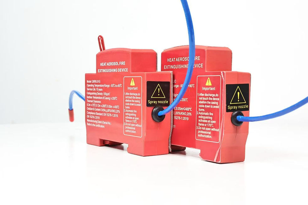
Clip-on mounting can suit a defined bracket or enclosure feature, but the matching profile and retention direction must be controlled. DIN rail mounting can provide a repeatable location, yet it consumes rail space and may affect adjacent component clearance. Adhesive mounting can avoid drilling, but it requires a qualified substrate, surface preparation, adhesive system, cure process, environmental range, and inspection plan. These mounting methods should not be swapped after approval without review.
For an application-specific layout example, see the MCB distribution box aerosol fire suppression guide. For adhesive process controls, review the adhesive-mounted aerosol fire suppression guide.
Build a Selection Evidence Matrix
The supplier's proposal should connect every design input to a controlled source. This matrix exposes gaps before a sample is installed.
Design decision: Evidence to request | Hold point
Product model: Datasheet and controlled drawing | Model identity or revision is unclear
Protected volume: Model-specific calculation method | Only a marketing volume is supplied
Hazard suitability: Test or approval scope and limitations | Protected materials or energized state are outside scope
Opening treatment: Documented leakage or closure method | Permanent openings are ignored
Quantity and arrangement: Calculation and placement drawing | Quantity cannot be traced to inputs
Activation method: Instructions and cause-and-effect logic | Trigger routing or interface is undefined
Mounting method: Bracket, rail or adhesive qualification | Mounting differs from tested configuration
Temperature range: Product and activator limits | Site conditions exceed stated limits
Inspection and service life: Maintenance instructions and replacement criteria | No controlled lifecycle information is available
Change control: Supplier revision and notification process | Substitutions can occur without approval
Verify the First Article Without Inventing Performance Data
First-article inspection should confirm enclosure dimensions, opening status, device identity, quantity, orientation, mounting retention, discharge clearance, activation routing, labels, and service access. Compare the completed assembly with the approved calculation and drawing. Photograph the final arrangement and record deviations.
Functionally test alarms, fan shutdown, interlocks, and upstream isolation using the manufacturer's approved non-discharge method. Do not trigger an aerosol unit merely to create an impressive demonstration. When a discharge test is required by the approval plan, use a controlled representative enclosure, documented instrumentation, defined pass criteria, and competent personnel. Preserve the report and state exactly which configuration it represents.
A visual inspection cannot prove extinguishing performance, and a successful test in one cabinet does not automatically cover every enclosure size or opening pattern. The acceptance decision should state the boundaries of the approved family, including permitted dimensions, volumes, components, ventilation states, mounting options, and activation arrangements.
Common Sizing Errors
- Using external cabinet dimensions instead of internal protected dimensions.
- Subtracting component volume without permission from the design method.
- Ignoring cable-entry leakage, open conduits, louvers, or connected compartments.
- Treating a maximum catalog volume as universal coverage.
- Changing clip-on, DIN rail, or adhesive mounting after sample approval.
- Placing the device where equipment blocks the discharge path.
- Assuming aerosol discharge isolates electrical energy or shuts down ventilation.
- Applying evidence from one enclosure configuration to a materially different cabinet.
- Quoting a standard number as if it were a product certificate.
- Accepting a supplier statement without controlled instructions, drawings, and test scope.
Frequently Asked Questions
Should aerosol sizing use gross or net enclosure volume?
Record gross internal volume first. Use net free volume only when the selected product's verified design method explicitly defines how occupied space may be deducted. Internal equipment can obstruct distribution, so subtracting it without a rule may understate the design requirement.
How should permanent ventilation openings be handled?
Measure and document every opening, then apply the treatment required by the selected system's standard, approval, or manufacturer design method. If the evidence does not cover the opening pattern, request an engineering review or representative application test rather than inventing a leakage allowance.
Can one calculation cover several cabinet sizes?
Only when the evidence defines an approved configuration family and its boundaries. The family should control dimensions, volume, openings, component layout, mounting, activation, ventilation state, and environmental limits. Otherwise, evaluate each enclosure configuration separately.
What information should be sent with an RFQ?
Send the enclosure worksheet, internal photographs, drawings, gross volume calculation, opening schedule, operating environment, hazard description, ventilation logic, preferred mounting method, activation concept, destination market, quantity, and required evidence package. SUNIOIO can then discuss the application without relying on assumptions.
Authoritative References
Contact SUNIOIO
For product selection, enclosure review, samples, OEM requirements, and quotations, use the SUNIOIO services page or contact SUNIOIO.
SUNIOIO / Yueqing Zhaoqing Electric Co., Ltd.
Phone / WhatsApp / WeChat: +86 13588953026


留言