
Clip-On Aerosol Fire Extinguisher Retention Validation: Tolerances, Gauges, and Tests

A clip-on aerosol fire extinguisher can be fast to install inside an electrical cabinet, but the snap sound alone is not evidence of secure retention. The mating profile, molded dimensions, cabinet feature, cable load, temperature, vibration, service access, and removal method all influence whether the unit stays seated without damage. Buyers and cabinet designers therefore need a controlled interface and a repeatable retention-validation plan, not a subjective push-and-pull check.

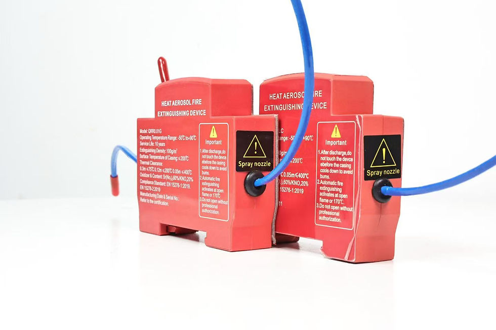
The production image used with this guide shows compact housings positioned in a manufacturing fixture. It is useful for discussing dimensional consistency and fixture control. It does not prove retention force, fire performance, activation temperature, protection volume, service life, or certification. Those claims require model-specific drawings and test evidence that match the supplied device, clip geometry, and target cabinet.
Define the clip-on interface before selecting a test
Treat the device and its receiving feature as one mechanical system. The drawing should identify the mating edge or tab, material, nominal thickness, allowable tolerance, insertion direction, stop surface, clip engagement depth, release direction, and any cable or activation-element path near the clip. A cabinet sample that is thicker, softer, more rounded, or more heavily coated than the approved drawing can change both insertion and withdrawal force.
For a snap-fit fire suppression device, record which component provides the spring action and which component provides the retention shoulder. If a molded hook flexes during installation, define the permitted deflection and inspect for whitening, cracking, permanent set, or interference after repeated cycles. If the cabinet feature flexes instead, include cabinet material and unsupported span in the interface specification.
The earlier clip-on mounting guide explains placement and service access. This article focuses on proving that the selected interface remains controlled across variation and use.
Establish evidence boundaries for the fire-protection product
ISO 15779:2026 covers requirements and test methods for condensed aerosol system components and gives recommendations for design, installation, testing, maintenance, and safety. Its public scope also states that local applications require a pre-engineered and pre-designed system tested and approved for the specific application by a relevant authority. A retention test is therefore only one part of application evidence; it cannot establish extinguishing performance by itself.
ANSI/CAN/UL/ULC 2775 addresses fixed condensed aerosol extinguishing system units within its stated scope, including construction and operation. Referencing that standard in a project specification does not mean an offered SUNIOIO unit is listed or certified. Verify the exact model, configuration, mounting option, report or listing, issuer, revision, installation conditions, and destination requirements before making a conformity claim.
Build a tolerance stack for the real cabinet
Start with controlled measurements from both sides of the interface. Measure the clip root, hook height, opening, engagement depth, housing datum, cabinet edge thickness, coating thickness, bend radius, local flatness, cutout position, and neighboring obstruction clearance. Use the same datums on the supplier drawing, incoming inspection, fixture, and cabinet drawing.
Do not add tolerances by intuition. Identify the worst material condition that creates maximum insertion force and the opposite condition that creates minimum engagement. Consider molding shrinkage, tool wear, post-mold conditioning, sheet-metal thickness, coating buildup, burrs, paint runs, and assembly position. A digital model can screen combinations, but production-representative samples must confirm the actual contact behavior.
Use a go/no-go gauge only for dimensions that directly control fit and can be measured without deforming the part. Keep master samples for visual comparison, but do not use an old part as the only dimensional standard. The OEM sample-approval guide shows how to freeze drawings, samples, labels, packaging, and records after qualification.
Separate insertion, seating, retention, and removal
Four different results should be recorded:
Insertion force: peak force needed to move the unit into the receiving feature.
Seating confirmation: evidence that the stop surface and retention shoulder reached the intended position.
Retention force: force required to disengage or move the unit in the defined withdrawal direction.
Removal force: controlled force and tool action needed for authorized service without damaging the cabinet or device.
Too little insertion force may indicate incomplete engagement or an oversized opening. Too much can damage the clip, push the cabinet feature out of shape, or encourage installers to use an unapproved tool. High retention force is not automatically better if service removal breaks the mounting feature or pulls on the activation lead.
Define force direction, pull point, fixture stiffness, loading rate, dwell time, and acceptance basis. A sideways pull, cable pull, direct housing pull, and shock load are different tests. Record the test setup with photographs and fixture drawings so another laboratory can reproduce it.
Clip-on retention validation matrix
Use a matrix tied to the risk assessment and the approved cabinet:
Test: Dimensional inspection; Controlled condition: Minimum, nominal, and maximum interface samples; Measurement: Critical dimensions and visual condition; Acceptance evidence: Drawing compliance and no damaged clip
Test: Insertion and seating; Controlled condition: Defined orientation and support; Measurement: Peak insertion force and seating indicator; Acceptance evidence: Within approved force window; full engagement
Test: Static withdrawal; Controlled condition: Specified direction and pull point; Measurement: Peak force or displacement under load; Acceptance evidence: No disengagement below approved limit
Test: Cable-load interaction; Controlled condition: Maximum permitted routed lead load; Measurement: Housing movement and clip condition; Acceptance evidence: No loss of seating or lead damage
Test: Temperature conditioning; Controlled condition: Project minimum and maximum non-operating conditions; Measurement: Insertion/retention before and after; Acceptance evidence: No unacceptable drift or cracking
Test: Vibration or transport simulation; Controlled condition: Approved profile and installed orientation; Measurement: Movement, damage, and post-test retention; Acceptance evidence: No release; post-test checks pass
Test: Service cycling; Controlled condition: Defined install/remove cycle count; Measurement: Force trend and visual damage; Acceptance evidence: Within limits; no permanent set or fracture
Test: Contamination review; Controlled condition: Defined dust, coating, or surface condition; Measurement: Seating and removal behavior; Acceptance evidence: Interface remains inspectable and serviceable
The table is a planning template, not a universal set of loads or cycles. Project engineers must define values from the device mass, geometry, cabinet environment, transport route, maintenance plan, and applicable requirements.
Create representative samples instead of testing only nominal parts
Nominal-to-nominal testing can hide the weakest combinations. Build or select samples that represent minimum engagement, maximum insertion, coating extremes, material-lot variation, mold-cavity variation, and the final cabinet production process. Identify every sample by device lot, mold cavity where traceable, cabinet lot, measurement record, conditioning, and test sequence.
Do not artificially machine a sample unless the change represents a real production limit and is documented. Artificial samples can be useful for development, but release decisions should include naturally occurring or production-controlled boundary samples. If the same housing supports clip-on, DIN rail, and adhesive options, keep the results separate because the load path and failure modes differ.
Inspect failure modes, not only the final force number
After every test, inspect the clip root, hook, stop, enclosure wall, fastener, lead exit, label, and discharge area. Look for whitening, cracks, permanent opening, gouging, loose fragments, coating removal, burr damage, housing distortion, lead pinch, blocked clearance, and unintended contact with energized equipment.
Record the failure location. A high pull value followed by cabinet-edge tearing is not a successful device-retention result. Likewise, a clip that remains attached while the housing shifts enough to obstruct the intended discharge path has failed the installation objective. Define maximum permitted movement and orientation change where relevant.
Use non-discharge tests for mechanical validation. Do not heat, flame, energize, puncture, or improvise activation of a live aerosol device. Any functional or fire test must follow an approved procedure in a suitable facility with the required safety controls.
Control the production fixture and measurement system
A production fixture should locate the part from the same functional datums used in the drawing. Identify fixture number, revision, calibration or verification method, permitted wear, check frequency, master part, and reaction plan. A fixture that merely holds a part in place may not verify clip geometry.
Perform a measurement-system review for critical gauges and force instruments. Confirm range, resolution, fixture compliance, alignment, zeroing, sampling rate, and operator method. Repeat measurements across operators and representative parts. When results are close to an acceptance limit, measurement uncertainty and fixture variation must be considered before disposition.
Link the result to the device lot and cabinet sample. A spreadsheet with only force values cannot show which mold cavity, coating thickness, conditioning state, or fixture revision produced them.
Installation and incoming-inspection checklist
Verify device part number, mounting option, lot, drawing revision, and approved cabinet interface.
Inspect the receiving feature for burrs, deformation, coating buildup, contamination, and obstruction.
Confirm orientation, clearance, discharge path, activation-element routing, and cable bend radius.
Install by the approved direction and hand/tool method; do not force a nonconforming fit.
Confirm the defined seating indicator, stop contact, and clip engagement.
Apply only the approved non-discharge retention check at the specified point and direction.
Verify the lead does not pull the housing, cross a sharp edge, or interfere with the clip.
Record device lot, cabinet identity, installer, date, result, and any deviation.
Quarantine mismatched or damaged parts and investigate the interface dimensions before rework.
After authorized removal, inspect both parts and follow the approved reuse or replacement rule.
Supplier and buyer approval questions
Ask the supplier for the controlled interface drawing, material specification, mold-cavity controls, critical dimensions, fixture plan, insertion and retention method, environmental conditioning, service-cycle rule, packaging restraint, lot traceability, and product change notification. Ask the cabinet supplier for edge geometry, material, coating, bend, cutout, local stiffness, tolerances, and process capability.
The buyer should approve the combined interface, not two independent drawings that have never been checked together. Freeze a golden assembly and boundary samples only after measurements and tests pass. The factory-audit checklist can then verify whether the supplier controls the same materials, tooling, fixtures, records, and release rules in production.
Frequently asked questions
Is a click during installation enough to confirm clip engagement?
No. A click can occur before full seating or from an unintended contact. Use a defined visual or dimensional seating criterion and a controlled non-discharge retention check.
What retention force should a clip-on aerosol fire extinguisher have?
There is no universal value. The required force depends on device mass, load direction, cabinet geometry, cable load, vibration, transport, service access, and the approved application. Define and validate a project-specific limit.
Can a nominal cabinet sample represent every production cabinet?
Not by itself. Validate relevant tolerance extremes, material and coating variation, manufacturing processes, and representative production lots from both the device and cabinet.
Can the clip be reused after the device is removed?
Only if the approved design and validation evidence allow reuse and post-removal inspection passes. Otherwise replace the specified mounting component or device according to controlled instructions.
Contact SUNIOIO
For clip-on aerosol fire extinguisher samples, interface drawings, cabinet-fit review, OEM options, and quotation support, contact SUNIOIO / Yueqing Zhaoqing Electric Co., Ltd.
Phone / WhatsApp / WeChat: +86 13588953026
Website: https://www.sunioio.com/ | Send an inquiry


留言