
Clip-On Aerosol Fire Extinguisher Mounting for Electrical Cabinets

A clip-on aerosol fire extinguisher is a compact automatic device held inside an electrical enclosure by a defined mechanical engagement rather than by adhesive alone. The mounting concept can simplify installation where a compatible edge, bracket, frame member, or purpose-designed receiver is available. It does not make placement universal: the clip geometry, retained load, discharge clearance, heat exposure, vibration, service access, and cabinet construction still have to be reviewed for the specific device and enclosure.
The words clip-on, snap-fit, and snap-on describe the retention method, not an approval, capacity, or fire-performance class. Buyers should obtain the manufacturer's current installation drawing, application limits, activation information, test evidence, and any authority requirements before specifying a unit. ISO 15779:2026 covers requirements and test methods for condensed aerosol system components and gives recommendations for design, installation, testing, maintenance, and safety. Its published scope also states that local applications require a pre-engineered, pre-designed system tested and approved for the specific application by a relevant authority. A small-cabinet installation therefore needs product- and application-specific evidence; a convenient clip does not replace that evidence.
Where clip-on mounting can be useful
Clip-on mounting is most useful when the cabinet provides a repeatable mechanical feature and the device can be fitted without drilling through the enclosure wall. Examples may include a purpose-made internal bracket, a formed metal flange, a compatible support rail, or a receiver supplied as part of an approved assembly. The exact interface must come from the product drawing. Do not assume that any sheet-metal edge is suitable or that a snap-on device can be transferred between unrelated cabinet families.
The method can be attractive in compact distribution boxes, control panels, meter enclosures, telecom cabinets, and small machine-control compartments because it may shorten assembly time and avoid surface-bonding variables. It can also make visual inspection straightforward: an inspector can check whether the retaining features are fully seated. However, space savings disappear if the device blocks breakers, terminals, wiring ducts, labels, ventilation paths, or normal maintenance access.
Clip-on mounting differs from adhesive-mounted aerosol fire suppression. Adhesive retention depends heavily on substrate condition, surface preparation, pressure, curing, and temperature. A mechanical clip depends instead on geometry, material stiffness, tolerances, engagement depth, resistance to release, and the strength of the cabinet feature receiving it. Neither method is inherently superior; the correct choice follows the tested configuration and the cabinet's constraints.
Define the mounting interface before selecting the device
Start with a dimensioned cabinet survey. Record the enclosure model, material, sheet thickness, coating, internal dimensions, door movement, cable-entry positions, energized parts, barriers, heat sources, ventilation openings, and service-removal path. Photograph the candidate mounting location with a scale. If the proposed clip engages a flange or bracket, measure its width, thickness, edge radius, flatness, and distance from nearby components.
Then request the corresponding device and clip drawing. The drawing should identify the permitted receiving geometry, insertion direction, required clearances, orientation limits, locked or seated indication, removal method, and any secondary retainer. A statement such as "fits most cabinets" is not an acceptance dimension. Use production-tolerance limits, not only a nominal dimension. A receiver at one end of its tolerance range and a clip at the opposite end can produce excessive insertion force or inadequate retention even when both individual parts appear acceptable.
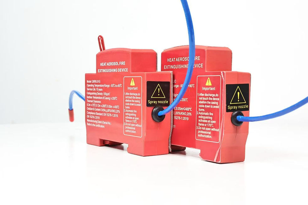
Do not confuse a purpose-designed clip with DIN rail mounting. A DIN rail-mounted fire suppression device uses a rail interface defined by the product arrangement; a clip-on product may engage a different feature entirely. Only describe a product as fitting a 35 mm DIN rail when its verified specification explicitly says so.
Cabinet-fit matrix
Use the following matrix during design review. It is a worksheet, not a declaration that every clip-on device is suitable for every enclosure.
Review item | Evidence to collect | Reject or escalate when
Receiving feature | Dimensioned cabinet and device drawings | Geometry is assumed from a photo or sample only
Engagement | Seating mark, latch position, insertion-force record | Clip is partly seated, distorted, or ambiguous
Retention | Approved pull, shock, or vibration test method | Device loosens, rattles, or can contact live parts
Discharge clearance | Manufacturer's installation envelope | Wiring, barriers, or apparatus obstruct the defined path
Thermal environment | Maximum measured cabinet temperature and device limits | Location is beside an unreviewed heat source
Electrical clearance | Cabinet layout and applicable equipment rules | Device or bracket compromises required spacing
Service access | Removal sequence and lockout procedure | Routine maintenance can dislodge the unit accidentally
Configuration control | Device, clip, receiver, enclosure, and revision IDs | A component can be substituted without revalidation
This matrix should be attached to the cabinet bill of materials or design record. A clip that works in one sample may fail after a sheet-metal supplier, coating thickness, bracket tooling, or device housing changes. Treat the receiving feature as a controlled interface, not as incidental cabinet hardware.
Placement is more than finding empty space
The installation location must satisfy the fire-suppression design as well as the mechanical fit. Review the protected volume, enclosure leakage, obstruction, ventilation, fuel type, energized equipment, activation arrangement, occupancy, and post-discharge procedures. The small-enclosure sizing guide explains why internal dimensions alone are not enough for selection.
Keep the device and its defined discharge region clear of loose conductors, insulation, labels, cable ties, plastic covers, and moving mechanisms. Do not place it where opening the door can strike it or where service tools are likely to catch the clip. Consider whether an internal fault could deform the mounting surface before activation. If the cabinet is exposed to vibration or transport shock, require evidence for the assembled device, clip, and receiver rather than relying only on a static hand-pull.
The mounting system must not create new electrical hazards. Any metallic bracket or receiver needs review for bonding, creepage and clearance, conductor abrasion, sharp edges, and proximity to energized terminals. Installation must be performed with the enclosure isolated according to the equipment manufacturer's procedure and applicable local rules. Fire protection and electrical design decisions should be approved by competent persons and the relevant authority where required.
UL Solutions identifies ANSI/CAN/UL/ULC 2775 as a standard for fixed condensed aerosol extinguishing system units and lists NFPA 2010 as an installation standard for fixed aerosol fire-extinguishing systems. Those references are useful evidence categories, but they do not justify claiming that an unverified product is listed, certified, or suitable for a particular cabinet. Ask for the exact certificate or report, model designation, scope, edition, issuing body, and validity before using any conformity statement.
Installation and acceptance procedure
1. Confirm identity. Match the device, clip, optional bracket, cabinet model, drawing revision, and activation components to the approved bill of materials. Quarantine substitutions until reviewed.
2. Make the enclosure safe. Isolate all energy sources, verify absence of voltage as required, and follow the cabinet manufacturer's lockout and access procedure.
3. Inspect the receiving feature. Check dimensions, coating damage, burrs, deformation, contamination, and interference. Do not bend a clip or cabinet flange to make an unapproved fit.
4. Check the installation envelope. Verify orientation, discharge clearance, cable routing, heat sources, ventilation paths, and access to terminals and protective devices.
5. Engage the clip as documented. Use the specified insertion direction and tools. Confirm the defined seated or locked indication without relying only on an audible click.
6. Inspect retention. Apply only the approved non-destructive check. Record whether the unit moves, rocks, rattles, or releases. A production check must not damage the device or substitute for qualification testing.
7. Complete activation checks. Verify thermal-cord or electrical connections only by the manufacturer's approved method. Never expose a live extinguishing unit to an improvised heat or flame test.
8. Restore and document. Photograph the finished installation, record serial or batch identity, inspector, date, cabinet location, and deviations, then replace barriers and covers.
For qualification, build a representative cabinet with production-intent tolerances and wiring. Subject it to the transport, shock, vibration, thermal, humidity, and service conditions that apply to the installation, using approved methods. Inspect clip engagement before and after each exposure. Any release, migration, cracked housing, damaged receiver, obstructed discharge area, or contact with live parts is a failed condition until dispositioned. Do not invent pass forces or cycle counts; derive them from the product specification, cabinet duty, applicable standards, and risk assessment.
Incoming inspection and maintenance record
Incoming inspection should compare the clip dimensions and material condition with the approved sample and drawing. Use a go/no-go gauge when the interface is critical and production volume justifies it. Check for molding flash, bent features, coating buildup, incomplete assembly, wrong bracket revision, and packaging damage. Keep a retained sample when the supplier or tooling changes.
After installation, maintenance should confirm that the device remains seated, unobstructed, dry, undamaged, and within the manufacturer's service requirements. Inspect after cabinet transport, internal rewiring, short-circuit repair, impact, unusual heating, water ingress, or replacement of the mounting bracket. Do not repeatedly remove and reinstall a snap-fit part unless the supplier defines the allowed cycles and inspection criteria. Replace damaged or weakened retention parts rather than reshaping them in the field.
The record should include cabinet ID, device model and batch, mounting interface revision, last inspection, observed condition, corrective action, and next due date. If several units loosen, stop treating the events as isolated workmanship errors and investigate tolerance stack, vibration, installation tools, and material changes.
Buyer and OEM questions
Ask the supplier to identify exactly which mounting interface has been evaluated with the quoted model. Request the device drawing, clip or bracket material, tolerance limits, installation instruction, allowed orientation, clearance envelope, activation method, environmental limits, maintenance requirements, and change-control process. If a certificate or test report is offered, verify that the model and configuration match the quotation.
The sample review should include at least three receiving-feature conditions: nominal, lower tolerance, and upper tolerance. Record insertion behavior, complete seating, removal behavior, post-vibration retention, and any damage. Agree on incoming inspection gauges, defect definitions, sampling, traceability, packaging restraint, and written approval for material or tooling changes. The OEM sample-approval guide provides a broader purchasing workflow.
Is clip-on mounting the same as DIN rail mounting?
No. Clip-on or snap-fit describes a mechanical engagement, while DIN rail-mounted equipment uses a specified rail interface. Some products may combine these ideas, but the supplier's drawing must confirm the exact arrangement and rail size.
Can the clip be fitted to any cabinet edge?
No. The receiving geometry, material, thickness, tolerances, orientation, retention, clearance, and environmental duty must match the approved installation. A visual resemblance is not adequate evidence.
Does a firm hand-pull prove the installation is safe?
No. It can be one controlled production check, but qualification may also need representative tolerance, shock, vibration, temperature, service, and fire-performance evidence. Use the product and cabinet acceptance plan.
References and contact
For a model-specific review, send the cabinet drawing, internal dimensions, receiving-feature dimensions, photos, operating environment, destination market, mounting preference, and required evidence through the SUNIOIO contact page.
SUNIOIO / Yueqing Zhaoqing Electric Co., Ltd. Phone: +86 13588953026


留言