
DIN Rail Fire Suppression Retrofit Survey for Crowded Control Cabinets

Retrofitting a compact fire-suppression device into an operating control cabinet is not a simple matter of finding an unused piece of rail. A credible DIN rail fire suppression retrofit begins with a documented survey of the enclosure, the existing electrical installation, the available service space, and the mounting path. The survey must also establish whether the proposed device and its activation method are approved for that specific enclosure application. A product photograph, nominal cabinet volume, or available rail length is not sufficient evidence by itself.

This guide focuses on the pre-installation work that cabinet builders, maintenance teams, distributors, and OEM buyers can perform before a model is selected. It does not assign an extinguishing-agent quantity, protection volume, clearance, service life, or approval status. Those values must come from the current manufacturer documentation and application-specific test or approval evidence.
The current ISO 15779:2026 page describes requirements and test methods for condensed aerosol system components and gives recommendations for design, installation, testing, maintenance, and safety. It also states that local applications require a pre-engineered and pre-designed system tested and approved for the specific application. UL Solutions identifies ANSI/CAN/UL/ULC 2775 as the standard for fixed condensed aerosol extinguishing system units and NFPA 2010 as an installation standard. These references are useful procurement checkpoints; mentioning them does not mean a particular SUNIOIO model is certified.
Why a crowded retrofit needs its own survey
A new cabinet can allocate space, cable routing, heat sources, labels, and maintenance access around the device. A retrofit inherits all of those constraints. The spare rail may sit behind a door-mounted harness, next to a contactor, below a ventilation path, or inside the required bend radius of a power cable. A position that looks empty with the door open can become obstructed when the door closes or when a technician removes a neighboring component.
The survey therefore has two objectives. First, it determines whether a candidate mounting zone exists without compromising the electrical design. Second, it creates the information package that the fire-suppression supplier and cabinet authority need to review the application. The output should be a controlled drawing or annotated photograph set, not an informal note that says “space available.”
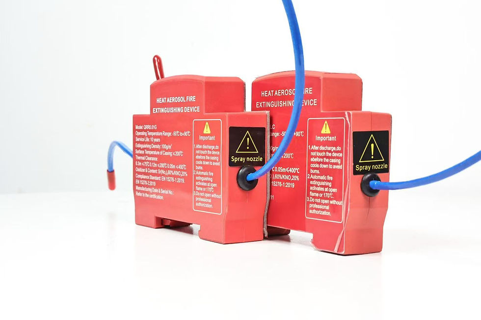
For a general introduction to the mounting concept, see SUNIOIO's DIN rail aerosol fire extinguisher guide. For enclosure measurement principles, use the separate small-enclosure sizing workflow. Neither page replaces model-specific instructions.
Record the enclosure before measuring the rail
Start with the cabinet identity: asset number, drawing revision, enclosure manufacturer, nominal dimensions, ingress-protection arrangement, supply voltage, major loads, location, and service environment. Record whether the cabinet is energized continuously, isolated during non-production hours, or subject to remote restart. Photograph the complete interior with the door fully open, then photograph the upper, middle, lower, and door zones without moving conductors.
Next identify existing heat sources and ignition-prone components, such as contactors, power supplies, variable-frequency drives, transformers, braking resistors, terminal blocks, and high-current joints. This is not a fire-cause conclusion. It is a map of components that may affect placement, temperature exposure, accessibility, or the approved protection arrangement.
Do not remove guards, move energized wiring, or work inside a live cabinet merely to improve a photograph. The survey must follow the site's electrical safety procedure, isolation rules, and qualified-person requirements.
DIN rail retrofit survey matrix
The following matrix is a practical deliverable for an RFQ. “Required value” means the project team must obtain the limit from the selected device documentation; the table does not prescribe a universal number.
Survey item: Rail profile; What to measure or verify: Profile type, section dimensions, material, and mounting method; Acceptance evidence: Drawing, measured profile, and cabinet record
Survey item: Free rail length; What to measure or verify: Continuous usable length after end stops and service allowance; Acceptance evidence: Dimensioned photograph with scale
Survey item: Front clearance; What to measure or verify: Distance to door, cover, duct lid, and door-mounted equipment; Acceptance evidence: Closed-door clearance measurement
Survey item: Side clearance; What to measure or verify: Distance to terminals, wire duct, relays, and removable modules; Acceptance evidence: Minimum measured value on both sides
Survey item: Cable bend zone; What to measure or verify: Conductors that enter, exit, or pass the candidate location; Acceptance evidence: Route sketch and bend-clearance check
Survey item: Rail support; What to measure or verify: Distance to rail fixing points and observed rail condition; Acceptance evidence: Photograph of rail fasteners and deflection check
Survey item: Heat exposure; What to measure or verify: Nearby heat-producing components and measured operating temperature; Acceptance evidence: Site measurement method and operating condition
Survey item: Activation route; What to measure or verify: Proposed thermal-cord or signal route, supports, and protected crossings; Acceptance evidence: Marked-up drawing reviewed against instructions
Survey item: Service access; What to measure or verify: Removal path for device and neighboring components; Acceptance evidence: Demonstrated tool and hand-access sequence
Survey item: Label visibility; What to measure or verify: Ability to read model, batch, date, warning, and inspection label; Acceptance evidence: Closed cabinet record plus service-view photo
Do not assume every rail is 35 mm. Only describe the installation as 35 mm DIN rail after the profile and selected product specification have both been confirmed. Also check whether the rail is structurally supported where the device will sit. A long cantilevered rail section can move during transport or maintenance even when the device appears secure during a static inspection.
Protect electrical clearances and maintenance access
The proposed device must not invade required electrical clearances, creepage paths, conductor bend space, ventilation paths, arc barriers, or component service envelopes. Those requirements depend on the cabinet design, voltage, equipment, jurisdiction, and manufacturer documentation. The retrofit review should therefore include the original cabinet builder or another competent authority who can approve modifications.
Pay particular attention to removable wire-duct lids. A device can fit beside a closed duct but block lid removal. Likewise, a technician may need to unplug a relay, tighten a terminal, or replace a power supply without disturbing the fire-suppression unit. If normal service requires removing the device, the maintenance instruction must define isolation, inspection, reinstallation, and replacement rules.
The activation route deserves a separate check. A thermal cord must not be treated as ordinary control wire. Its location, support, proximity to heat sources, minimum bend conditions, and interfaces must follow the approved instructions. SUNIOIO's thermal-cord routing and test guide explains how to record the route without claiming an unverified activation threshold.
Estimate rail and transport loads without inventing limits
The device supplier should provide mass, mounting orientation, approved rail profile, retention method, and any environmental or vibration limits. The cabinet team can then assess static load, rail deflection, transport direction, door shock, and service handling. Do not create a generic retention-force requirement from the device mass alone. Dynamic loading, rail stiffness, clip geometry, cable forces, and enclosure vibration all matter.
As a clearly hypothetical screening example, assume a candidate device has a documented mass of 0.40 kg and the project engineer uses a preliminary 5g transport acceleration only for fixture planning. The inertial load would be 0.40 × 9.81 × 5, or about 19.6 N. This is not an acceptance criterion and not SUNIOIO test data. The final test level and direction must come from the applicable product, cabinet, transport, and project requirements.
Staged non-discharge acceptance checklist
Installation acceptance should verify mounting and interfaces without activating the extinguisher. Use the approved inert sample, gauge, or installation method when the manufacturer specifies one.
Confirm the cabinet is in the approved safe state and the work permit is active.
Match the device model, mount, orientation, rail profile, instructions, and drawing revision.
Inspect the rail, supports, end stops, coating damage, deformation, and contamination.
Verify the measured clearances against the approved installation drawing.
Install the device using the specified sequence and record full seating or locking evidence.
Check that wire ducts, barriers, covers, and neighboring modules remain removable as intended.
Close the door slowly while observing harness movement and final clearance.
Verify the activation route and supports without applying heat or an unauthorized electrical signal.
Record label visibility, serial or batch identity, installer, date, and inspection result.
Perform only the approved non-discharge checks; never improvise a live activation test inside production equipment.
The record should include exceptions and corrective actions. A pass/fail box without measurements is weak evidence, especially when multiple cabinet variants share one project number.
What buyers should request from a supplier
An RFQ for a DIN rail-mounted fire suppression device should include cabinet drawings, internal photographs, rail details, free-space measurements, operating temperature information, component layout, activation concept, destination market, and expected inspection process. Ask the supplier to identify the exact model, mounting hardware, orientation, application limits, installation instructions, marking, batch traceability, storage conditions, and the evidence supporting any performance or certification claim.
Request representative samples and drawing-controlled dimensional data before approving production. Verify that the delivered mount matches the approved rail and that normal lot variation is included in the inspection plan. A supplier should also state what must be replaced after activation, removal, transport damage, expired service period, or a failed inspection.
Frequently asked questions
Can unused DIN rail space alone approve the retrofit?
No. The review must also address electrical clearances, rail support, door and duct movement, heat exposure, activation routing, maintenance access, product instructions, and application-specific approval evidence.
Can the cabinet stay energized during the survey?
Only under the site's approved electrical safety program and qualified-person rules. Measurements that require access near energized parts should be avoided or completed under the required controls; this article does not authorize live work.
Does ISO 15779 automatically approve a cabinet installation?
No. ISO 15779 is a system standard and reference point. Its existence does not certify a device or approve a particular retrofit. Obtain model-specific evidence and the approval required for the project and jurisdiction.
Should a retrofit installer perform a discharge test in the cabinet?
Not as an improvised acceptance step. Use approved non-discharge checks and follow the manufacturer, system designer, authority, and site procedures for any commissioning or discharge testing.
Contact SUNIOIO
For a model-specific review, send the cabinet drawing, internal photographs, verified rail profile, measured clearances, operating conditions, destination market, and required approval basis through the SUNIOIO contact page.
SUNIOIO / Yueqing Zhaoqing Electric Co., Ltd. Phone: +86 13588953026


留言