
Thermal Cord Routing for Aerosol Fire Extinguishers: Inspection and Non-Discharge Tests

A thermal cord activated fire extinguisher inside an electrical cabinet depends on more than the aerosol generator itself. The thermal activation element must be routed close enough to the intended hazard to respond, yet far enough from normal hot parts, sharp edges, moving doors, high-current conductors, and service tools to avoid damage or unwanted operation. The approved product manual, cabinet risk assessment, and application test evidence remain controlling; this guide explains how to turn those requirements into a repeatable routing and inspection record.
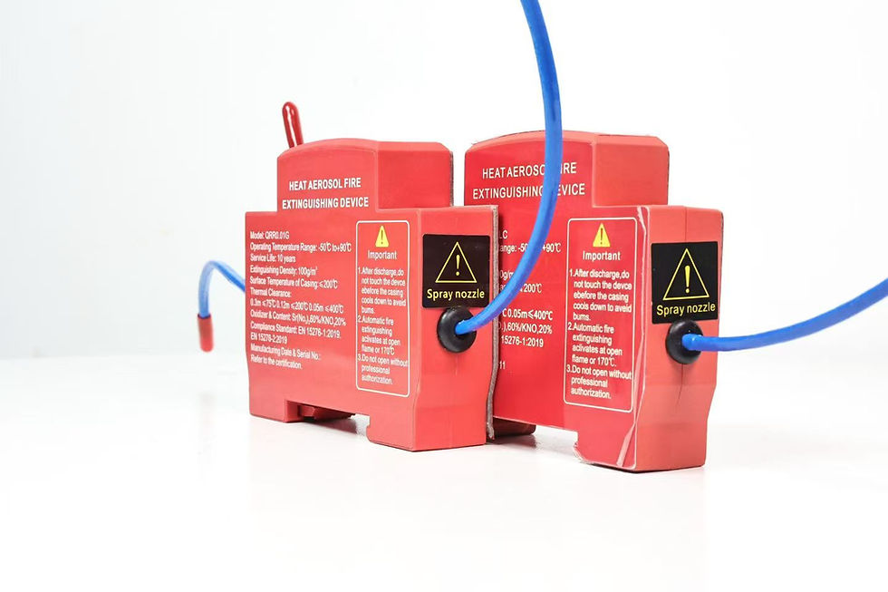
The red cabinet device shown here is a real compact product image. Its visible label is not used as evidence for ratings, certifications, protected volume, service life, or activation temperature. Those facts must be verified for the exact ordered model and project.
Define the activation boundary before drawing the route
Start with a compartment drawing, not a loose cord laid around components. Mark the protected enclosure, ignition sources, normal heat sources, airflow openings, cable entries, door travel, service zones, and the proposed aerosol discharge area. A cabinet with separated busbar, control, and power-conversion compartments may need separate hazard reviews because heat and aerosol do not necessarily move freely across barriers.
Identify what the thermal element is intended to detect. It may be a localized abnormal temperature near a terminal, contactor, power supply, or cable joint. It is not a substitute for every other form of detection, nor does it automatically provide a remote alarm. If the project requires alarm transmission, power isolation, fan shutdown, or restart inhibition, define those functions separately in a cause-and-effect matrix.
Do not select a routing temperature by looking at a cabinet's maximum ambient rating. The activation temperature, exposure duration, installation geometry, nearby surface temperature, airflow, and thermal inertia all affect response. Obtain the permitted routing method, bend limits, joint rules, termination details, and non-initiating test procedure from the manufacturer.
Separate abnormal heat from expected operating heat
Measure or obtain credible temperature data for normal operating states. Include maximum design load, high ambient temperature, closed-door operation, fan failure where relevant, solar gain for outdoor enclosures, and temporary heat after shutdown. A thermal cord routed against a resistor, heat sink, transformer, inverter, or warm exhaust path can experience a high local temperature without a fire.
Create two maps: a normal-temperature map and a hazard map. The first identifies where activation must not occur during rated service. The second identifies credible early fire locations. The route should respond to the second without being dominated by the first. When measurements are unavailable, use conservative engineering review and a controlled temperature survey before final approval; do not invent a universal separation distance.
The small-enclosure aerosol sizing guide explains why volume, openings, airflow, and obstructions must be recorded together. Routing is part of the same enclosure-specific design process.
Routing zones and prohibited conditions
Divide the cabinet into routing zones and assign an acceptance rule to each.
**Candidate hazard zone:** At terminals, contactors, cable joints, or compact power supplies, route only where the approved element can sense the hazard without electrical interference. Retain the drawing, measured clearance, and normal-temperature survey.
**Normal hot zone:** At resistors, heat sinks, transformers, or fan exhausts, avoid the route unless the product-specific design permits the exposure. Retain the maximum measured temperature and manufacturer limit.
**Mechanical damage zone:** At hinges, sharp edges, removable panels, or tool-access areas, reroute the element or add an approved protective feature. Record door-cycle and service-access inspection.
**High-current zone:** Near busbars, exposed terminals, or power cables, maintain required electrical clearance and avoid creating a conductive or tracking path. Retain the clearance review and controlled drawing.
**Airflow zone:** Near fan inlets, outlets, louvers, or filters, evaluate whether airflow delays heating or carries hot gases away. Record each operating-state airflow review.
**Cable-entry zone:** At glands, conduits, or field-wiring areas, prevent pulling, crushing, or accidental shortening. Verify the installation with a controlled pull check.
This table is a planning artifact, not a product specification. The project engineer must replace general descriptions with the actual device instructions, cabinet drawings, and acceptance values.
Never route the activation element loosely across live parts, through an unprotected sheet-metal opening, under a clamp intended for power cables, or where a technician will use it as a tie point. Do not splice, shorten, extend, paint, tape over, or bundle it unless the exact product instructions permit that action. Cable ties can create stress points or change thermal exposure; use only the approved retention method.
Coordinate the route with the mounting method
The mounting method changes the likely cord route. A DIN rail-mounted aerosol fire extinguisher may sit near control devices, but the route still has to avoid terminals, rail clips, and removable modules. A clip-on aerosol fire extinguisher can simplify assembly where the cabinet has a validated receiving feature, but the clip and the activation element must both survive door movement and service vibration.
For adhesive mounting, surface preparation, cure condition, cable pull, and aging become important because a displaced device can change both discharge orientation and thermal-element tension. Record the exact device location, route, retention points, bend geometry, and termination on the controlled assembly drawing. A photograph supports the record but does not replace dimensional definition.
Build a safe non-discharge test plan
The acceptance test must prove installation and control behavior without accidentally initiating the device. Never apply a meter, test current, heat source, flame, or improvised continuity test directly to an initiator unless the manufacturer's written procedure explicitly authorizes the instrument and method.
Use this sequence:
Isolate hazardous energy under the site's approved procedure and verify the safe work condition.
Confirm cabinet model, revision, protected compartment, device model, lot, and controlled drawing.
Inspect the aerosol device for damage, contamination, altered labels, unauthorized openings, or expired replacement date where applicable.
Trace the complete thermal element from the device to its termination without pulling it.
Verify retention points, bend condition, clearance from sharp edges, door travel, service tools, normal hot surfaces, and live components.
Compare the route with the approved drawing and record deviations before energization.
Use an approved simulator or isolated test input to verify alarms, shutdown, fan response, remote indication, restart inhibition, and event logging.
Restore energy only after tools, temporary links, simulators, and protective barriers have been accounted for.
Run the cabinet through defined normal operating states and confirm that nothing contacts, heats, stretches, or abrades the route.
Sign the acceptance record with instrument IDs, drawing revision, photographs, measured observations, tester, reviewer, and date.
The phrase “non-discharge test” is important. Heating the real activation element as an acceptance shortcut can consume or damage it, create an uncontrolled release, or invalidate the installed condition. Functional discharge testing belongs in a controlled qualification program using the manufacturer's approved arrangement and safety controls.
Non-discharge acceptance record
A practical inspection sheet should contain the following fields:
Cabinet and compartment identification.
Aerosol device model, serial or lot, and approved documentation revision.
Thermal-element type, route drawing, termination, and retention method.
Minimum observed electrical clearance and the project requirement used for comparison.
Closest normal hot component and its highest validated operating temperature.
Door, cover, filter, fan, and removable-module interference result.
Approved simulator or test method used for cause-and-effect checks.
Alarm, isolation, fan, remote signal, and restart results.
Deviations, disposition, photographs, instrument IDs, signatures, and date.
Use pass, fail, or not applicable for each item. Blank cells are not acceptance. If the route differs from the approved drawing, stop and process the deviation through engineering review; do not accept it only because the cord appears intact.
Troubleshooting without creating a new hazard
If a supervisory circuit reports a fault, first confirm the architecture. The thermal element, electrical release circuit, alarm input, and device body may be separate items. Check drawings, connectors, terminals, and approved diagnostic indicators before disturbing the route. Do not bridge a safety input to clear an alarm for production.
For intermittent faults, correlate event time with door movement, fan operation, vibration, maintenance, and temperature. Look for pinched leads, loose approved connectors, abrasion, moisture, contamination, or unauthorized field repair. A fault that disappears when a door is moved is evidence of a routing problem, not evidence that the system is healthy.
After any cabinet modification, repeat the route review. Replacing a contactor, adding a drive, changing a fan, moving a harness, installing a new gland, or altering a cover can create a hot zone, interference point, or airflow change. Update the drawing and maintenance register so later inspectors know what was approved.
Buyer and supplier evidence review
Ask the supplier for the exact installation manual, activation-element specification, permitted routing and retention methods, storage and transport limits, non-initiating test method, traceability, production checks, and application test evidence. A standard number printed on a label is not proof that the ordered model holds a certification.
ISO 15779:2026 covers requirements and test methods for condensed aerosol components and for system design, installation, testing, maintenance, and safety. Its scope also makes clear that local applications require a pre-engineered or pre-designed system tested and approved for the specific application. UL Solutions' fire-extinguishing system testing page identifies ANSI/CAN/UL/ULC 2775 and NFPA 2010 among relevant references. These sources guide due diligence; they do not establish that a SUNIOIO product or any quoted device is certified.
For OEM procurement, freeze the approved route drawing, critical activation components, retention parts, inspection points, and supplier change-notification rules. A substitute cord, connector, adhesive, clip, or enclosure location can change the response and must not enter production without review.
Frequently asked questions
Can a thermal cord touch power cables inside a cabinet?
Do not assume that it can. Electrical clearance, insulation compatibility, normal cable temperature, fault heating, mechanical movement, and the manufacturer's routing rules must all be reviewed. Use the approved drawing and product instructions.
How close should the thermal element be to a likely ignition point?
There is no universal distance. Response depends on the activation element, temperature threshold, heat release, airflow, obstruction, orientation, and product-specific application evidence. Define the distance through approved engineering and testing.
Can a multimeter be used to test the activation circuit?
Only when the manufacturer specifies the permitted instrument, range, connection point, and procedure. An improvised meter test can apply unsafe energy to an initiating circuit. Use an approved simulator or non-initiating method.
Must the route be reinspected after cabinet service?
Yes when service can affect location, tension, clearance, airflow, hot components, or door movement. Compare the finished work with the controlled drawing and repeat applicable cause-and-effect checks before return to service.
Contact SUNIOIO
For thermal cord activated fire extinguisher selection, cabinet routing review, samples, and OEM documentation, contact SUNIOIO / Yueqing Zhaoqing Electric Co., Ltd.
Phone: +86 13588953026
Website: https://www.sunioio.com/


留言