
EV Charger Cabinet Aerosol Fire Suppression: Placement and Acceptance

EV charger cabinet fire suppression must be engineered around the actual enclosure, ignition sources, ventilation paths, energized conductors, maintenance access, and emergency response plan. A compact aerosol device can be one layer of protection for a small electrical compartment, but it is not a substitute for fault prevention, overcurrent protection, thermal monitoring, enclosure design, or site fire protection. It also must not be represented as a proven method for stopping lithium-ion cell thermal runaway unless the exact product and application have supporting test evidence.
This guide focuses on AC/DC distribution and power-electronics compartments inside EV charging equipment. It gives charger manufacturers, panel builders, installers, distributors, and buyers a repeatable way to define the protected space, choose a mounting position, coordinate activation and shutdown, and document acceptance. All example values are illustrative; the approved product instructions, risk assessment, authority having jurisdiction, and destination-market rules control the final design.
Define the protection boundary before selecting a device
Start by dividing the charger into real compartments. A freestanding charger may contain an incoming AC section, surge protection, contactors, busbars, rectifiers, DC output switching, controller electronics, fans, filters, cable terminations, and communication equipment. Some designs also have separate battery-buffer modules. These spaces can have different fire hazards, airflow, access, and isolation behavior.
Record the internal free volume of each compartment rather than using the outside cabinet dimensions. Subtract major components only according to the approved design method. Document doors, louvers, cable glands, fans, ducts, drainage openings, and pressure-relief features. A device intended for a small, substantially enclosed space may not maintain an effective concentration in a continuously ventilated or highly leaky enclosure.
Do not combine an electrical cabinet and a battery module into one vague protection claim. An aerosol device placed near contactors may be evaluated for an incipient electrical-component fire, while battery cells can release heat and flammable gases through a different failure mechanism. Any claim concerning cell thermal runaway, propagation, explosion control, or battery fire performance needs application-specific evidence.
EV charger cabinet survey worksheet
| Survey item | Evidence to collect | Design decision | | --- | --- | --- | | Compartment free volume | Drawing plus measured dimensions | Device coverage basis | | Normal airflow | Fan curve, operating modes, vent area | Leakage and retention assessment | | Credible ignition points | FMEA, thermal scan, fault history | Placement and detection priority | | Voltage and available fault current | Electrical schematic and protection study | Isolation and service procedure | | Cable and busbar routes | Layout drawing and photographs | Keep discharge and heat paths clear | | Access and removable panels | Service procedure | Prevent accidental damage or removal | | Ambient range | Site specification | Product suitability review | | Shutdown interfaces | Controller I/O and contactor logic | Alarm, isolation, and restart sequence | | Battery presence | Exact module and test evidence | Separate thermal-runaway analysis |
Keep this worksheet in the design file and link every assumption to a drawing, test, or approved specification. If the enclosure changes, repeat the review instead of carrying over a device quantity from an older model.
Map ignition sources and obstruction zones
Typical charger ignition concerns include loose terminals, overloaded connections, contactor wear, insulation damage, contaminated circuit boards, blocked cooling, fan failure, surge events, and component defects. Use thermal imaging, torque-control records, protection coordination, and design FMEA to rank locations. The goal is not to predict one perfect ignition point; it is to avoid placing the device where its discharge and heat path are blocked by a large component or where activation would be delayed by an isolated pocket.
Mark keep-clear volumes around busbars, creepage and clearance paths, moving fan parts, air filters, door hinges, service handles, and high-temperature components. Check that the device body, activation element, cable, clip, rail adapter, or adhesive pad cannot bridge conductors or compromise insulation distances. Confirm that the selected mounting surface remains stable through normal vibration and temperature cycling.
The installation must preserve access to fuses, disconnects, terminal covers, labels, and test points. Service technicians should not need to remove the suppression device for routine electrical work. If removal is unavoidable, use a controlled procedure and a record that verifies correct reinstallation.
Choose a mounting method from the cabinet construction
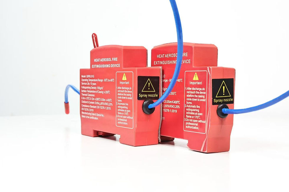
A clip-on or snap-fit mount can suit a repeatable bracket or enclosure feature when the geometry, retention force, material aging, and vibration duty have been validated. A DIN rail-mounted device can simplify controlled placement in a rail-based control compartment, but only when rail profile, available width, locking method, electrical clearances, and removal access match the approved hardware. Do not assume every rail is 35 mm unless the product specification and cabinet drawing confirm it.
Adhesive mounting can be useful where drilling is prohibited, but surface condition becomes a safety-critical input. Review substrate material, coating, flatness, contamination, humidity, temperature, cable pull, cure time, and aging. The adhesive-mounted cabinet guide explains surface preparation and acceptance controls. Do not identify an adhesive by a brand name unless the exact supplied material has been verified.
For an EV charging cabinet, select the method that can be inspected and controlled in production. Record the device orientation, fastener or retention detail, activation-element routing, minimum clearance, and unique installation point on the assembly drawing. A photograph alone is not a controlled engineering definition.
Coordinate activation, alarm, and electrical shutdown
Activation architecture may be thermal, electrical, or a combination, depending on the approved device. Define what initiates discharge, what supervisory signal is available, and what the charger does before and after activation. Do not connect a thermal element, release circuit, or monitor input without the manufacturer's permitted wiring and the charger control-system review.
A project-specific cause-and-effect matrix should state the response to high temperature, smoke or off-gas signal, suppression activation, cabinet-door opening, emergency stop, communication loss, auxiliary-power loss, and contactor feedback disagreement. Possible actions include stopping charging, opening upstream and downstream contactors, isolating auxiliaries, alarming locally, transmitting a remote event, disabling automatic restart, and requiring inspection. The safe order depends on the charger topology and fault study.
Electrical isolation does not instantly remove every hazard. DC-link capacitors can retain voltage, conductors can remain energized from vehicle or supply interfaces, and damaged equipment may reignite. Mark residual-energy controls and emergency instructions. Only qualified personnel should inspect an activated or fire-damaged charger.
Placement review for a charger cabinet
Use a drawing review followed by a physical fit check. The candidate position should support the approved discharge geometry and activation response while avoiding direct contact with live parts. Consider whether fan operation could immediately carry aerosol out of the protected compartment. If shutdown stops the fans, confirm the timing relative to detection and activation. If fans continue for thermal management, evaluate the consequence using test evidence rather than intuition.
Check the device and activation element against foreseeable service actions: filter replacement, connector tightening, module removal, door closure, cable flexing, and cleaning. Route the activation element so it cannot be mistaken for a signal wire or tied into a high-current harness. Protect it from sharp edges and unauthorized shortening.
The cabinet manufacturer should freeze the approved location in the bill of materials and work instruction. A field installer should not relocate the device merely because another surface is easier to reach. Changes require a documented engineering review.
Non-discharge installation acceptance checklist
Verify charger model, enclosure revision, compartment identifier, device model, lot, and approved drawing.
Measure the protected free volume and confirm openings, fan configuration, and major obstructions match the design record.
Inspect the mounting interface for correct rail, clip, bracket, or prepared adhesive surface.
Confirm orientation, retention, keep-clear distances, electrical clearances, activation-element route, and label visibility.
Perform the approved pull, vibration, or retention check without damaging the device.
Verify release-circuit continuity or supervisory status using the manufacturer's non-initiating test method.
Test alarm, charger shutdown, contactor feedback, remote notification, restart inhibition, and event logging without commanding discharge.
Inspect door movement, service access, fan operation, filter replacement, and cable movement for interference.
Record photographs, instrument IDs, measured results, firmware, drawing revision, installer, inspector, and date.
Seal or control the installation according to the approved work instruction and update the maintenance register.
Never improvise an electrical test across an initiator. Use only an approved tester and procedure with current and energy below permitted limits. If there is doubt, stop and obtain written instructions from the device supplier.
Illustrative enclosure review
Assume a charger has a separated AC distribution compartment and a power-conversion compartment. The AC section is compact and has no forced ventilation; the conversion section has two continuously operating fans and large internal obstructions. The engineering team should not automatically install identical devices in both spaces.
For the AC section, the team can document free volume, terminal hot spots, possible mounting locations, shutdown logic, and retention tests. For the ventilated conversion section, it must additionally determine airflow states, fan shutdown timing, leakage, obstruction effects, and whether the selected system has evidence for that geometry. The result may be a different device arrangement, a different fire-protection method, or a decision that the proposed aerosol device is unsuitable. This example illustrates the decision process, not a product rating.
Maintenance and change control
Include the device in charger inspection schedules. Check mounting security, corrosion, contamination, physical damage, cable or activation-element condition, obstruction, labels, expiry or replacement criteria stated by the manufacturer, and changes to fans or cabinet openings. Verify that firmware updates have not altered alarm or shutdown behavior.
After any cabinet repair, component relocation, fan replacement, filter redesign, cable-routing change, or enclosure modification, repeat the fit and cause-and-effect checks. A small mechanical change can alter free volume, airflow, heat transfer, or discharge obstruction. Keep service records by charger serial number.
An activated device and fire-exposed equipment require controlled replacement and investigation. Preserve logs, photographs, damaged parts, and protection-device status. Do not re-energize until the charger OEM or authorized competent person has approved the repair and the required electrical tests are complete.
Buyer and supplier evidence package
Buyers should request the exact product data sheet, installation manual, application limits, activation description, storage and handling requirements, mounting drawings, traceability, production test plan, conformity evidence applicable to the destination, and test reports that identify the tested model and configuration. A logo or standard number printed on a label is not enough to prove certification.
ISO 15779:2026 covers requirements and test methods for components and system design, installation, maintenance, and safety of condensed aerosol firefighting systems. Its published scope notes that local applications require a pre-engineered, pre-designed system tested and approved for the specific application. UL Solutions' fire-extinguishing system testing page identifies ANSI/CAN/UL/ULC 2775 and NFPA 2010 among the relevant standards. These references support due diligence; they do not prove that a quoted product holds any certification.
For OEM sourcing, define sample approval tests, drawing control, critical materials, change notification, lot traceability, packaging protection, incoming inspection, and nonconformance handling. Use the SUNIOIO OEM sample-approval guide to structure the review, then adapt it to the charger project and destination market.
Frequently asked questions
Can one aerosol device protect an entire EV charger?
Not automatically. The answer depends on compartment volume, separation, leakage, airflow, obstructions, ignition hazards, device performance evidence, and the approved application design. Treat each real protected space as an engineering boundary.
Does cabinet aerosol suppression stop battery thermal runaway?
It must not be assumed. Electrical-component fire suppression and lithium-ion cell thermal runaway are different hazards. Any thermal-runaway or propagation claim requires evidence for the exact battery and system configuration.
Should charger fans stop when suppression activates?
The cause-and-effect sequence must be engineered and tested. Fan shutdown may help retention in some designs, but timing, heat removal, gas behavior, residual energy, and product instructions must be considered.
What is the most important installation record?
Maintain a controlled drawing and acceptance record that links the charger revision, protected volume, device model and lot, mounting location, activation route, measured checks, shutdown test, photographs, and inspector.
Contact SUNIOIO
For EV charger cabinet fire-suppression device selection, mounting review, samples, and OEM documentation, contact SUNIOIO / Yueqing Zhaoqing Electric Co., Ltd.
Phone: +86 13588953026
Website: https://www.sunioio.com/


留言